Last year I saw these fluorescent lamps from the Omega company that were used to display huge “bildboard” signs.
No, blue LEDs have not been evented yet.


MatHertel blogging about current activities. I am currently focusing on DMX related hardware and software on the Arduino platform.
Last year I saw these fluorescent lamps from the Omega company that were used to display huge “bildboard” signs.
No, blue LEDs have not been evented yet.
I like to share some liks to the ressources on the internet that I found helpful for implementing projects using the Ultra low power 2.4GHz RF Transceiver NRF24L01+ with the Arduino platform.
The NRF24L01 (no + at the end) was replaced by the NRF24L01+ (or sometimes called NRF24L01P). Be sure to get the new chip when buying an breakout board.
The nRF24L01+ is drop-in compatible with nRF24L01 and on-air compatible with nRF2401A, nRF2402, nRF24E1 and nRF24E2. Intermodulation and wideband blocking values in nRF24L01+ are much improved in comparison to the nRF24L01 and the addition of internal filtering to nRF24L01+ has improved the margins for meeting RF regulatory standards.The old chip: http://www.nordicsemi.com/eng/Products/2.4GHz-RF/nRF24L01
The new chip: http://www.nordicsemi.com/eng/Products/2.4GHz-RF/nRF24L01P
You should read the nRF24L01+DataSheet, even if it is long and with many details – but that’s what you will need: http://www.nordicsemi.com/eng/content/download/2726/34069/file/nRF24L01P_Product_Specification_1_0.pdf
This is a nice to read whitepaper with a description of the ShockBurstTM transfer features of the chip:
http://www.semiconductorstore.com/pdf/NewSite/nordic/WP_nRF240x_ShockBurst.pdf
There is no official “Arduino” library that is maintained by the core Arduino team so you have to look for the available libraries on the internet.
The web site http://www.tinkerer.eu/ from Stefan Engelke in 2009 provides a native NRF20L01 library, the original MiRF library (not Arduino specific) and a native SPI library See http://www.tinkerer.eu/AVRLib/nRF24L01, and http://www.tinkerer.eu/AVRLib/SPI . I mention this library because it uses interrupts that most Arduino samples don’t.
The MiRF library was ported to the Arduino platform and is using the Arduino SPI library and is described on the arduino playground article: See http://playground.arduino.cc/InterfacingWithHardware/Nrf24L01
J. Coliz (a.k.a. maniacbug) implemented a ARDUINO specific library often called the RF24 library. Its available at https://github.com/maniacbug/RF24/ and was used as the base for implementing other libraries (see below) the last commit to this projects was last on 2012/06/23.
Greg Copeland forked (copied over) the library from maniacbug and added some useful stuff including a scanner sample application. He is currently (2013.04.09) supporting his work. See https://github.com/gcopeland/RF24.
Arco van Geest (a.k.a. gnulnulf) also forked the library from maniacbug is currently adding support for the Raspberry Pi. See https://github.com/gnulnulf/RF24
Stanley Seow forked the version gnulnulf https://github.com/stanleyseow/RF24 also working on upport for the Raspberry Pi.
There are too much libraries out there for my opinion and those starting from J. Coliz are using the GNU General Public License (not LGPL) and therefore are not compatible with the Arduino license policy.
J. Coliz also used the stdio.h printf() functionality ??? causing more usage of the program memory
For my personal projects I used the library from Greg Copeland for my first steps to discover the functionality of the chip.
Poor Man's 2.4 GHz Scanner:
http://arduino.cc/forum/index.php/topic,54795.0.html
Home Automation – Designing a remote module:
http://geekboy.it/projects/home_automation/home-automation-design
Sample without using a library:
http://blog.iteadstudio.com/nrf24l01-wireless-module-with-arduino/
A sample using the MiRF library:
http://www.bajdi.com/playing-with-nrf24l01-modules/
Step-by-Step introduction using the RF24 library:
http://arduino-info.wikispaces.com/Nrf24L01-2.4GHz-HowTo
Network Layer for RF24 Radios:
http://maniacbug.github.io/RF24Network/index.html
A very detailed tutorial in German:
http://www.mikrocontroller.net/articles/NRF24L01_Tutorial
These links are not related to Arduino itself but when reading you may also find some interesting information.
...
I wrote this small Arduino library more than 2 years ago for some of my projects to use a single input button for multiple purposes. This library detects clicks, doubleclicks and long press situations without a lot of coding on the sketch side.
This enables you to reuse the same hardware button and input pin for several functions and lowers the hardware invests.
I just updated it including a new sample that shows how to setup the library and bind a "machine" that can blink the LED slow or fast.
See Arduino OneButton Library on my side.
I currently work on an project using the popular NRF24L01 module where I came across the question how to avoid conflicts of new designs and existing Arduino boards.
The problem when using the W5100 based Ethernet shield including the SD Card adapter and the NRF24L01 Modules together with a Arduino UNO board is that all of them are using the same SPI bus for the data transfer to the chips. Here is an overview of how to make them work all together.
Here the master is always the same ATMEGA328 chip on the Arduino board and the 3 chips are slave devices.
A brief explanation of the SPI bus can be found on wikipedia. See http://en.wikipedia.org/wiki/Serial_Peripheral_Interface_Bus
The SPI bus needs 4 signals to work:
SCK or SCLK (serial clock) The clock signal that sets the tempo for any data transfer. This signal is generated by the master chip.
On the Arduino Uno this signal is available on pin 13 and ICSP 3.
MISO (master input, slave output) This signal line transfers the data from a slave device to the master chip.
On the Arduino Uno this signal is available on pin 12 and ICSP 1.
MOSI (master output, slave input) This signal line transfers the data from the master to the slave devices.
On the Arduino Uno this signal is available on pin 11 and ICSP 4.
SS or CSN (Slave Select) This signal makes a slave active by selecting it with a low signal.
On the Arduino Uno this signal has to be discussed…
Remark: The signal lines SCK, MOSI and MISO are also available on the ICSP header, see below.
The signal lines SCK, MOSI and MISO can permanently remain connected to all participating chips. However the Slave Select signal has to be different for every device.
The SPI signals on an Arduino Mega board are not available on the pins 10, 11, 12 and 13 because this board uses another processor. But because programming an ATMEGA chip through the ICSP is internally also using the SPI interface, the signals are available on the ICSP header too. With the Arduino Ethernet Shield Version 06 the design has changed so that the SPI signals are not taken from the pins 11, 12 and 13 but from the pins ISP 4, 1 and 3. If you use an Arduino UNO or 2009 however these pins are connected on the main board. When designing new shields for Standard and MEGA boards with SPI usage I recommended using the ICSP header like the Ethernet Shield does.
When using multiple slave devices on the same SPI bus there is no principle problem with the lines SCK, MOSI and MISO. Because every slave device needs its own slave select signal there are conflicts using the available Arduino pins. When you stack multiple ARDUINO shields on a single Arduino board you may also have conflicts with other pins the shield uses so you have to take care of other conflicts too. Here are some common pin usages:
| Arduino Shield | Salve device | Arduino Pin |
| Ethernet version 01 | W5100 chip Slave Select | 10 |
| Ethernet version 06 | W5100 chip Slave Select | 10 |
| Ethernet version 06 | SD card Slave Select | 4 |
In different samples where the NRF24L01 radio is using the Arduino pin 9 for SS and using pin 8 for the Chip Enable signal but also 8 and 7 is used in same samples. There is no standard definition right now and therefore you have to tell the NRF24L01 library what signals to use for Slave Select and Chip Enable.
I personally recommend using 7 for Chip Enable and 8 for Slave Select because the pin 9 is one of the possible PWM output pins. When designing new Shields these pins assignments should be changeable in any way, just to be friendly to other shields… and having the chance to settle conflicts.
Design of the Arduino Ethernet Shield: http://arduino.cc/en/Main/ArduinoEthernetShield
Using the SD-Slot on the EthernetShield with Hardware SPI: http://playground.arduino.cc//Main/EthernetShieldSDHardwareSPIMod General tutorial: http://tronixstuff.wordpress.com/ About the NRF24L01: http://playground.arduino.cc/InterfacingWithHardware/Nrf24L01 I just published the version 1.0 of the DMX RDM library as an Arduino library with sample code.
Download the file from http://www.mathertel.de/Arduino/DMXSerial.aspx, unzip the file to your Sketches\libraries and try the example in libraries\DMXSerial2\examples\RDMSerialRecv.
The hardware requirements for that sample is a DMX line attached to the serial port, the data direction switch at pin 2 and some led to the ports 5, 6 and 9.
The schema of the DMX shield documented in http://www.mathertel.de/Arduino/DMXShield.aspx can be used as well.
Any feedback is welcome.
The first versions (up to version from 22.01.2013) of DMXSerial2 was not stable during several tests I did and often a response package did not reach the controller as expected.
After some testing with inserted delayMicroseconds() functions and time probes in several places I found that the implementation with the Arduino processor and the DMX Shield was sometimes too fast for the used controllers and the DMX line.
In several publications for example in http://www.soundlight.de/techtips/dmx512/dmx_rdm.htm you can find the timing requirements defined by the RDM standard and it seems that it is very important to follow them strictly.
The one timing condition that is indeed implemented by the RDM client is the time between the end of a RDM command that is sent by the controller and the start of the RDM response that is sent by the client.
Because the answer to a command is created asynchronously in the tick() function this time was varying and was often shorter than the expected minimal 176 µsec .
The version from 01.03.2013 and later now saves the time when the last byte of a command was sent into a global variable and delays the start of the answer when appropriate. After implementing this delay mechanism the RDM communication was much more stable then before.
And there is the RDM-BREAK that is longer than the DMX-BREAK: min. 176 µsec instead of 88 µsec.
I published the updated Arduino project today. It’s still work in progress and a library format will be available soon.
I just published an new Arduino project on my web site that implements an DMX RDM Device using the DMXShield.
From the beginning the DMXSerial library was designed to send and receive DMX data packets. Now it is extended to support RDM packets as well. I had to overcome several pitfalls and stumbling blocks while extending the DMXSerial implementation and I will keep the current version because it needs only a very small amount of program data. The RDM extended version will be DMXSerial2.
What you can find in the attached zip file right now is an ARDUINO project including all the files you need to compile. Because it is still in WIP (work in progress) I did not extract the DMXSerial2 files into a library format yet.

The last weeks I spent some time in extending the DMXSerial library for Arduino to support the DMX - RDM protocol by using the DMX Shield for Arduino.
A prototype version (proof of concept state) is already working. So now I know that the layout of the shield is RDM compatible.
But there is still some work to do for the library. I’ll try to publish a new version of the DMX library in some weeks.
If you are interested in co-working please let me know.
Some new DMXShields arrived, tested and running fine.
I already updated the article www.mathertel.de/Arduino/DMXShield.aspx and updated the eagle files in the zip file too even if the text is still related to an older version.
If you have interest in buying one of the PCBs – just let me know.
 I just updated the article on my DMXSpot project.
The schema and the PCB eagle files are available in the download from the article.
Thank to Jonathan L for this brilliant work on fixing some timing conditions with the sending side of the DMXSerial library.
From his comment:
I'm sure the existing timings (81us break) are pretty much fine with almost all DMX inputs, even though the spec says that the transmitted break time needs to be >= 92 us with MAB >= 12 us. Nonetheless I was motivated to fix it to be as close to 100 us/12us as I could, as this is what is transmitted by most of the commercial DMX units I've seen.
The real issue would be if you ran this on a faster processor, in which case the timings would break when the interrupt service routine became faster than the byte time. I was running this on 16 MHz Atmega 328. Most of the ISR is spent doing the long division inside DMXSerialBaud(): I replaced it with a compile-time calculation of the prescaler value, and this results in trashing the last data byte and the break. You can see the results in attached timing23.png.
Happily all is fixed by the changes, although the code is a bit more complex.

I studied the changes to the routines and I understand h did everything. It's all well commented and I like his programming style too. I loaded it into a project I have done some months ago and it works fine.
I personally haven't used much the sending part of the library. The last projects were lighting systems that are controlled by DMX used the receiving part only and I found it reliable but he fixed a buffer bug in this too.

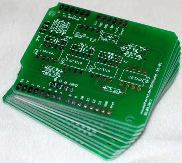
After 2 weeks of waiting the first shipment of the PCB board finally arrived.
I can not wait to soldering the parts together.
My first impression is that the arrangement of the components fits well. If I find out that the circuit works as intended, I'll publish the Eagle files on my website.

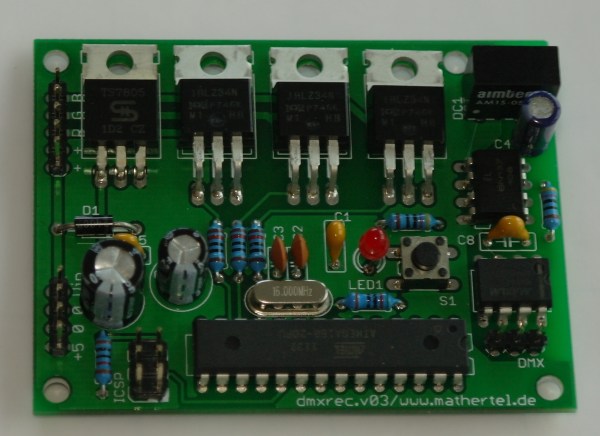
The aim of this project is to build a small PCB board for RGB LED installations and to use the DMX protocol for controlling.
I build this board because I want to have a permanent and robust solution for light installations and I like to release my Arduino board for other projects.
Also, when using a standard Arduino board there are many components built in that are not used at all. For a simple DMX solution the ATMEGA 168 that was used in older Arduino versions is powerful enough and still provides enough memory for complex programs. So all you can find on this board are the minimum components for a 3 channel DMX receiver and the components to drive LEDs with a voltage around 12 volts or higher.
Because I started with an Arduino board many characteristics of the Arduino design remain:
The additional parts compared to the Arduino board are the chips of the communication interface that is able to receive DMX signals including an isolation and 3 Mosfet chips for driving LEDs.
The board uses only standard through-hole soldering components allowing an easy building for hobbyists like me.
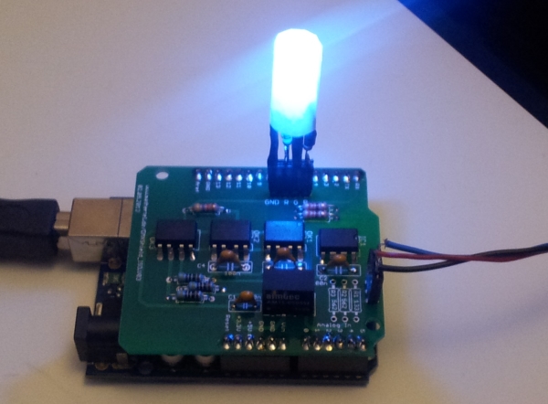
Here are some pictures of the Arduino assembly and from my first prototype.
There where several problems with the first version so I had to patch some wires and add some components on the back. Not good enough to be published.