Showing posts with label DMXSerial. Show all posts

03 September 2017

Arduino based DMX device for controlling NeoPixel and WS2811

In the DMXSerial library examples folder you now can find a sketch for receiving DMX with an Arduino and send the received data to a series of NeoPixel or WS2811 LEDs. Just load the DMXSerial library version 1.4 using the library manager of the Arduino environment of download DMXLibrary from Github.


The challenge for this sketch was the fact the both protocols, DMX and WS2811, are time critical and that the standard Arduino Uno processor doesn’t have the power to do both protocols at the same time.


The solution for this is another DMX mode in the DMXSerial implementation that allows to stop the DMX protocol while sending out the data to the NeoPixels.


DMXProbe mode


This mode is starting the Arduino in DMX receiving state, but doesn’t actively listen for incoming data. No interrupts are enabled and any incoming data packet will stick in the serial receiver.


To receive data the receive() function must be called. This function clears all hardware buffers and waits for an incoming data package by using the same mechanism as the DMXReceiver mode. After receiving a package this function returns with true and data can be found in the internal buffer.


When no DMX data was received in the specified time the receive function will return false.


The DmxSerialNeoPixels example


This example contains a sketch for receiving DMX data with an Arduino and send the received values to a series of NeoPixel or WS2811 LEDs.

The NeoPixel sending routine is based on the work of bigjosh2 from his positing on his web site:
https://wp.josh.com/2014/05/13/ws2812-neopixels-are-not-so-finicky-once-you-get-to-know-them/


The DMXSerial library is not yet published as a new version to the Arduino community. I just like to push it out to all of you working with time critical implementations as an added value and check for problems during the next days.


14 April 2015

The DMX library DMXSerial for Arduino is now available using the Arduino Library Manager

From now on it’s easy to install and update the library by using the Library Manager in the Arduino environment including including 3 sample applications for sending and receiving DMX messages.

I used several of the beta versions and also the final to test compatibility of my DMXSerial library.

By using the Library Manager you can always download the latest stable version that is tagged with the version number directly in my github repository.

You can find that repository directly at:

If you haven’t already done so, please download the new Arduino environment version 1.6.3 or later from the Arduino web site www.arduino.cc.


If you like the latest version including work in progress please use the download from github directly by using a git or subversion client. If you like to contribute I like to see your attributions based on this version.

03 April 2014

Improved DMX Shield Version for Arduino

The last version of the shield with it’s features and internals can be found on http://www.mathertel.de/Arduino/DMXShield.aspx .

This new version of the shield has no functional additions, so it works exactly like the shield in version v03 that is in use in multiple installations. But there are some improvements by adjusting some values and make its use more flexible when using it on top of an Arduino MEGA and other shields.

The most obvious features of the new (V04) version of the DMX Shield are the better placements of some of the components and the addition of all the shield connectors from the current Arduino boards.

Fixes to resistor values

The values from the optocoupler OK3 transferring the receiving signal in version v03 are adapted to the other optocouplers.

The 3 resistors (R4, R5, R6) are used to limit the current for the internal LEDs of the optocouplers. They had 300 or 470 Ohm in the first layout. These values are now made equal to 470 Ohm which is sufficient.

The 3 resistors (R7, R8, R9) are used to pull the output value of the optocoupler to HIGH also had different values of 470 or 4,7k Ohm. These values are now also made equal to 4,7k Ohm which is also sufficient. The downside of it is that the resistors are hard to distinguish.

I use both adjustments in some installations and they run fine.

The error in the naming of R1 and R2 is fixed.

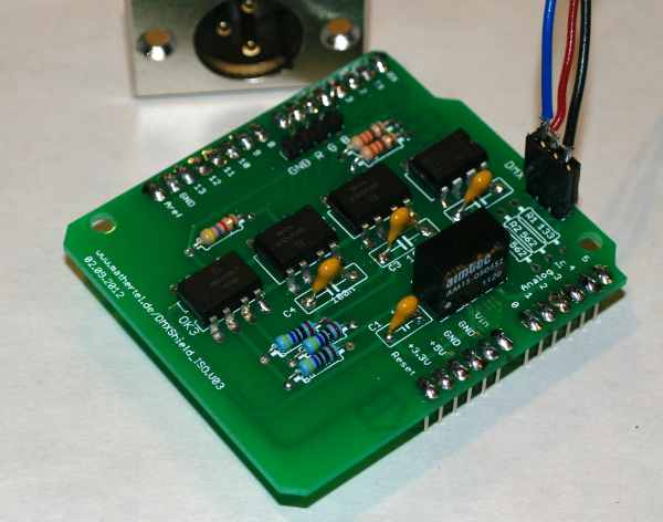
Here is a picture of the shield with some assembly hints:

DMXShield.v04.hints

Flexibility for Arduino MEGA

The signals RX, TX and D2 are now brought to the pins d0, d1, d2 via a solder jumper. These 3 jumpers should be closed by dropping a small part of solder upon them for normal operation with Arduino Uno or Leonardo Boards.

If you like to use other serial ports or signals like on the Arduino MEGA you can leave these jumpers open and connect the signals the way you like.

The ICSP header of the Arduino board can now be brought to the next shield above the DMX shield by soldering a stackable header.

All the 4 holes from the Arduino Uno Board are now also available to the shield for building permanent robust stacks.

ICSP header and more pins.

All of these extensions are not needed by the DMX shield but it is a good practice to have connection pads and holes at these positions so the signals can be passed through.

Some Arduino shields are using the ICSP header to access the SPI signals from the ATmega chip. The Ethernet shield is a good example for that and there are good reasons to do so.

Not the new version of the DMX shield has 6 contacts right where a ICSP connector can be soldered to pass through the signals to a shield above.

Also 2 of the Arduino header pins have been expanded since some versions. The POWER connector is now 8 pins long and includes IOREF signal. The upper digital connector is now 10 pins long and include the SDA and SCL signals.

Because the DMX shield does not need these signals you can leave these pins without soldering a header or use the (old) shorter headers if you like.

Partlist DMX Shield

Here are the parts you need for a full assembly. It’s also a good order of soldering them.

Part name Value Description
Starting with the low parts...

R4, R5, R6

470 Ω

Bands: (yellow, purple, black, brown, brown*) or (yellow, purple, brown, silver*)

R7, R8, R9

4,7 kΩ

Bands: (yellow, purple, black, black, brown*) or (yellow, purple, red, silver*)

The resistors R1 - R3 should be adjusted for the role of the DMX board in your DMX setup.
This configuration is for a DMX / RDM Controller. Don't use them when implementing a DMX or RDM Slave.

R1, R3

562 Ω

Bands: (green, blue, red, black, brown*)

R2

133 Ω

Bands: (brown, orange, orange, black, brown*)

Now the capacitators...

C1,C2,C3,C4

100n

Capacitors stabilizing the power. Label: 104

The dc-dc converter...

DC1

NME 0505

A dc-dc-converter. The chip that provides another 5 v source for the DMX signal converter.

Now you can check if the secondary 5v power is existing. Put it on top of an Arduino and measure the voltage at the capacitor C4. It should be near by 5V.

The optocouplers and the driver chips...

IC1

MAX481CPA

A MAX481CPA or MAX485 CPA from Maxim or another supplier used to convert the differential DMX signal into a logical signal.
The 8 pin chip can be soldered directly or put on a socket. Be sure to place it in the right direction.

OK1, OK2, OK3

6N137

The optocouplers.
The 8 pin chip can be soldered directly or put on a socket. Be sure to place it in the right direction.

...and the connectors

DMX


1X03 pinhead. I cut it from a longer (20 pin) one.

RGB


1X04 pinhead

stackable headers


You can solder the usual stackable headers or if you use the shield at the uppermost shield on the Arduino you can solder simple pinheads too.

ICSP


There is no need caused by this shield to solder a ICSP. You can solder one if you like to use the shield with another shield above that needs these connections.

solder jumpers


Don’t forget to close the jumpers when using a standard Arduino.

I will update the article on the web during the next days and will attach some pictures too.

I ordered more than I need for my projects so if you are interested in the PCB – let me know.

14 December 2013

Arduino DMX libraries now also available on Github


In the last weeks I got some very valuable feedback and some corrections for the DMXSerial2 library for Arduino from Felicitus and he asked me to put the sources into the GitHub repository.

I am used to work with Subversion and never worked with Git before but everything runs perfectly. I love the way how someone can add merge requests to an existing repository without the need to manage users and roles.

So you can find the library now on:
https://github.com/mathertel/DmxSerial2.

You can download the complete library including the samples by using the “Download ZIP” button on the right-hand side or by using the link
https://github.com/mathertel/DmxSerial2/archive/master.zip

I plan to also leave a copy of the other Arduino libraries there.

31 August 2013

DMXBridge, a wireless DMX sender and receiver

There are situations where DMX cables are unwanted or just not practical. This project implements a wireless transfer of a DMX signal in the 2.4 GHz band using the Arduino platform and the popular transceiver module nRF24L01+ from nordic semiconductor.

The DMX protocol

Receiving and sending the DMX protocol from the ATmega chip is done by using the DMXSerial library and the built-in serial port. This implementation is using interrupts and is a good base for implementing a second protocol on the same chip.

The DMX Serial library has a built-in 512 byte buffer for a DMX universe that is accessible using the functions provided by the library. After initializing the library and starting the communication the interrupts ensure the communication in the background.

You can find a lot of details in the article about the DMXSerial library.

The Wireless protocol

The 2.4GHz RF Transceiver is connected to the Arduino board or ATmega processor by using the SPI interface. The library for driving this chip I used is the library from Greg Copeland that you can find at https://github.com/gcopeland/RF24. After initializing the library it is possible to send and receive data by using the provided functions of the library. The library transfers all the commands and data to the nRF24L01+ chip will also handle all the transfer details in the background.

Implementation

Because the libraries handle most of the communication details the implementation of this project only has to close the gap between the 2 protocols. The main differences between them are

Frame size: DMX is using a max. 512 byte long frame for sending all the values of all channels at once. The Transceiver uses a much shorter protocol that can transfer up to 32 bytes in one frame. I have seen controllers that do not send all the 512 bytes when only some channels are used in the setup.

Transfer speed: DMX is constantly using a 250 kBaud serial transfer speed on the DMX wire. There may be longer gaps between the frames and also between the individual bytes of a frame but it is common to use the maximum possible transfer speed. The Transceiver is supporting 3 different transfer modes

The solution I found and implemented here is to break up the 512 channels of the DMX information into smaller packages.

The sender

There are 2 buffers of DMX values. One contains the values I have received lately from the DMX protocol. The DMXSerial library is used to listen to the DMX protocol and fill this buffer.

The second buffer contains the values that have been sent over the wireless.

The values of both buffers are compared to find the recent changes and to send them with priority. If there is no difference between the 2 buffers no priority data will be sent.

To enable the addition of new receivers and to heal dropped packages all the DMX data is sent from time to time regardless whether there are changes on not.

The package transferred wirelessly contains a start-address and the actual 8 values starting at this address. The sender just sends the package without requesting any handshake from the receiver. This is called the broadcast mode of the nRF24L01+ modules that enables to use multiple receivers.

The receivers

The receiver only needs a single DMX buffer. All data from the incoming packages is directly taken into this buffer.

The DMXSerial library is used to send this information using the DMX protocol.

Setup the hardware

Both, the sender and the receivers need the DMX interface hardware attached to the serial interface and a nRF24L01+ module attached to the SPI bus. A prototype for this setup I used is the DMX Shield I published and a hand-soldered nRF24L01 adapter. The DMX shield is not forwarding the ICSP pins yet so this will only work on the Arduino UNO and older boards. (See discussion in Arduino Shield for NRF24L01+ post).

You need 2 of these at minimum.

Setup the software

Now you should be able to open and compile the provided sketches and upload them to the Arduino hardware.

The sketches I can provide for now are working in my environment and are not yet optimal for rough environments like stages. There are still some optimizations to do like sending smaller or larger packages and testing different transfer speeds. I like to get feedback from you.

Links

26 August 2013

DMXSerial Update

I just updated the Arduino Library for DMX with some improvements in memory and speed as well as some minor changes.

Thanks to Jenny for the hints.

If you use this library please download the newest version from: http://www.mathertel.de/Arduino/DMXSerial.aspx

01 July 2013

Another DMXSerial example

The DMXSerial library for the Arduino that you can find at http://www.mathertel.de/Arduino/DMXSerial.aspx has only 2 small examples that show the principle functionality of the DMX library:

  • DMXSerialRecv implements a 3 channel DMX device on channel 1-3 and sends the data to the PWM output pins 9, 6 and 5.
    It also shows the usage of the DMXSerial.noDataSince method.
  • DMXSerialSend implements a 3 channel DMX Controller sending a continuously changing color schema to the channels 1 to 3.
    Here an array of color definition is used and the implementations adjusts the current color smoothly into the next color from the arrays.

Now there is a new example available:

DMXSerialFlow implements a 60 (20*3) channel DMX Controller sending a continuously changing colors schema to the channels 1 to 3.

The calculation of the colors is done by using a hue to rgb converter.

Hue is a number from 0 to 764 that represents one of the colors of a color wheel. With a simple algorithm it is possible to calculate the red,green and blue component of it.

There are some hints inside the code that allows you to make some changes for example the speed of the color changing.

This example was used for testing a wireless 2.4 GHz DMX transceiver that I am working on right now. Stay tuned :-)

19 May 2013

Update for the DMXSerial library

There is a significant update for the DMXSerial library on my web site that enables programming DMX devices on ARDUINO MEGA boards and ARDUINO Leonardo boards using the DMXSerial library.

The original library was written for Arduino 2009 and Arduino UNO boards that use the ATmega328 or ATmega168 chip. These chips only have a single Universal Synchronous and Asynchronous serial Receiver and Transmitter (USART) a.k.a. the Serial port in the Arduino environment. The DMXSerial library uses this port for sending or receiving DMX signals.

This conflicts a little bit with the usage of the programming mode the Arduino offers through then USB ports or serial interfaces but it is possible to build compatible DMX shields that don’t interfere with this usage if done right. The DMXShield is an example of this.

Arduino Leonardo

The Arduino Leonardo board uses a chip that has a USB 2.0 port available in addition to the USART. Therefore the “Serial” port is routed through the USB port that behaves like a serial port device and not the built-in USART. If you like to address the real Serial port you have to go with the Serial1.

But if you look at the hardware and the registers directly the USART0 still exists but the definitions for addressing the registers have changed (for example USART_RX_vect is now USART0_RX_vect). Therefore some adjustments had to be done.

With this board you can write debugging information to the Serial port in your sketch for debugging or data exchange purpose. So maybe a DMX diagnostic sketch can profit from that.

Arduino MEGA 2560

When using the chip on the Arduino MEGA 2560 board you have more than one USART available and maybe you wish to use port 1 instead of port 0. This can be done by enabling the definitions for port1 in the library just uncomment the line

#define DMX_USE_PORT1

ATmega8 boards

I added the definitions of boards based on the ATmega8 too for experimental purpose. If you find problems with these boards, leave me a note please.

Thanks to Bob Lynas to support me.

Available

The updated version is available on my site at: http://www.mathertel.de/Arduino/DMXSerial.aspx.

08 March 2013

DMX RDM library DMXSerial2 Version 1.0 released

I just published the version 1.0 of the DMX RDM library as an Arduino library with sample code.
Download the file from http://www.mathertel.de/Arduino/DMXSerial.aspx, unzip the file to your Sketches\libraries and try the example in libraries\DMXSerial2\examples\RDMSerialRecv.

The hardware requirements for that sample is a DMX line attached to the serial port, the data direction switch at pin 2 and some led to the ports 5, 6 and 9.

The schema of the DMX shield documented in http://www.mathertel.de/Arduino/DMXShield.aspx can be used as well.

Any feedback is welcome.

01 March 2013

DMXSerial2 Update

The first versions (up to version from 22.01.2013) of DMXSerial2 was not stable during several tests I did and often a response package did not reach the controller as expected.

After some testing with inserted delayMicroseconds() functions and time probes in several places I found that the implementation with the Arduino processor and the DMX Shield was sometimes too fast for the used controllers and the DMX line.

In several publications for example in http://www.soundlight.de/techtips/dmx512/dmx_rdm.htm you can find the timing requirements defined by the RDM standard and it seems that it is very important to follow them strictly.

The one timing condition that is indeed implemented by the RDM client is the time between the end of a RDM command that is sent by the controller and the start of the RDM response that is sent by the client.

Because the answer to a command is created asynchronously in the tick() function this time was varying and was often shorter than the expected minimal 176 µsec .

The version from 01.03.2013 and later now saves the time when the last byte of a command was sent into a global variable and delays the start of the answer when appropriate. After implementing this delay mechanism the RDM communication was much more stable then before.

And there is the RDM-BREAK that is longer than the DMX-BREAK: min. 176 µsec instead of 88 µsec.

I published the updated Arduino project today. It’s still work in progress and a library format will be available soon.

See http://www.mathertel.de/Arduino/DMXSerial2.aspx

10 January 2013

DMX Shield for Arduino is also working with RDM

DMX Shield for Arduino

The last weeks I spent some time in extending the DMXSerial library for Arduino to support the DMX - RDM protocol by using the DMX Shield for Arduino.

A prototype version (proof of concept state) is already working. So now I know that the layout of the shield is RDM compatible.

But there is still some work to do for the library. I’ll try to publish a new version of the DMX library in some weeks.

If you are interested in co-working please let me know.

11 August 2012

Important DMXSerial Library update

Thank to Jonathan L for this brilliant work on fixing some timing conditions with the sending side of the DMXSerial library.

From his comment:

I'm sure the existing timings (81us break) are pretty much fine with almost all DMX inputs, even though the spec says that the transmitted break time needs to be >= 92 us with MAB >= 12 us.   Nonetheless I was motivated to fix it to be as close to 100 us/12us as I could, as this is what is transmitted by most of the commercial DMX units I've seen.

The real issue would be if you ran this on a faster processor, in which case the timings would break when the interrupt service routine became faster than the byte time.  I was running this on 16 MHz Atmega 328.  Most of the ISR is spent doing the long division inside DMXSerialBaud(): I replaced it with a compile-time calculation of the prescaler value, and this results in trashing the last data byte and the break.  You can see the results in attached timing23.png.

Happily all is fixed by the changes, although the code is a bit more complex.

I studied the changes to the routines and I understand h did everything. It's all well commented and I like his programming style too. I loaded it into a project I have done some months ago and it works fine.

I personally haven't used much the sending part of the library. The last projects were lighting systems that are controlled by DMX used the receiving part only and I found it reliable but he fixed a buffer bug in this too.