20 December 2012

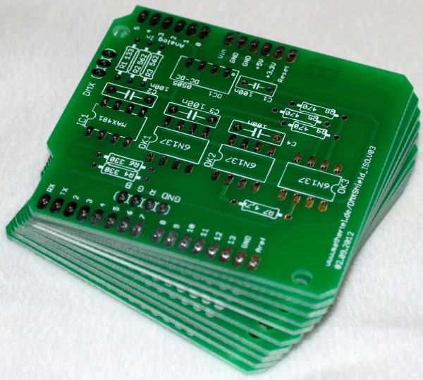
New DMX Shields available

Some new DMXShields arrived, tested and running fine.

I already updated the article www.mathertel.de/Arduino/DMXShield.aspx and updated the eagle files in the zip file too even if the text is still related to an older version.

If you have interest in buying one of the PCBs – just let me know.

01 September 2012

DMX Receiver version 03 is running

I just updated the article on my DMXSpot project.

This picture shows the fist good version of the PCB for building simple LED projects with DMX control. It
contains only the parts needed to receive a DMX signal including the isolation parts known from the DMXShield and 3 MosFets that can drive some amperes of load. That should be enough to control a huge amount of LEDs or some power LEDs.


  The schema and the PCB eagle files are available in the download from the article.

11 August 2012

Important DMXSerial Library update

Thank to Jonathan L for this brilliant work on fixing some timing conditions with the sending side of the DMXSerial library.

From his comment:

I'm sure the existing timings (81us break) are pretty much fine with almost all DMX inputs, even though the spec says that the transmitted break time needs to be >= 92 us with MAB >= 12 us.   Nonetheless I was motivated to fix it to be as close to 100 us/12us as I could, as this is what is transmitted by most of the commercial DMX units I've seen.

The real issue would be if you ran this on a faster processor, in which case the timings would break when the interrupt service routine became faster than the byte time.  I was running this on 16 MHz Atmega 328.  Most of the ISR is spent doing the long division inside DMXSerialBaud(): I replaced it with a compile-time calculation of the prescaler value, and this results in trashing the last data byte and the break.  You can see the results in attached timing23.png.

Happily all is fixed by the changes, although the code is a bit more complex.

I studied the changes to the routines and I understand h did everything. It's all well commented and I like his programming style too. I loaded it into a project I have done some months ago and it works fine.

I personally haven't used much the sending part of the library. The last projects were lighting systems that are controlled by DMX used the receiving part only and I found it reliable but he fixed a buffer bug in this too.

11 June 2012

The DMX spot PCBs finally arrived

arrived

After 2 weeks of waiting the first shipment of the PCB board finally arrived.

I can not wait to soldering the parts together.

My first impression is that the arrangement of the components fits well. If I find out that the circuit works as intended, I'll publish the Eagle files on my website.

14 January 2012

DMX Spot project

The aim of this project is to build a small PCB board for RGB LED installations and to use the DMX protocol for controlling.

I build this board because I want to have a permanent and robust solution for light installations and I like to release my Arduino board for other projects.

Also, when using a standard Arduino board there are many components built in that are not used at all. For a simple DMX solution the ATMEGA 168 that was used in older Arduino versions is powerful enough and still provides enough memory for complex programs. So all you can find on this board are the minimum components for a 3 channel DMX receiver and the components to drive LEDs with a voltage around 12 volts or higher.

Because I started with an Arduino board many characteristics of the Arduino design remain:

  • The processor can be a Atmel ATMEGA168 or ATMEGA328.
  • The clock speed is 16 MHz.
  • The surrounding elements like the capacitors have the same values.
  • The software implementation uses the Arduino environment.
  • I can reuse all the source code I have written so far for my Arduino.

The additional parts compared to the Arduino board are the chips of the communication interface that is able to receive DMX signals including an isolation and 3 Mosfet chips for driving LEDs.

The board uses only standard through-hole soldering components allowing an easy building for hobbyists like me.

Here are some pictures of the Arduino assembly and from my first prototype.

There where several problems with the first version so I had to patch some wires and add some components on the back. Not good enough to be published.